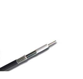
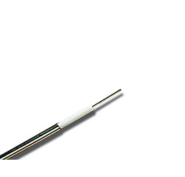
UHF series cable provides the lowest insertion loss in the current industry, and has excellent mechanical phase, temperature phase, and attenuation stability. And has good processing ability for power bearing. This is achieved through a cabl...
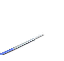
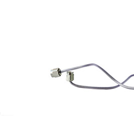
UHS series cable is the super-flexible type of ultra-low loss stable-phase cable. In the market application experience, ultra-low loss stable-phase cable in meeting customer requirements for electrical performance, in actual use, there are s...
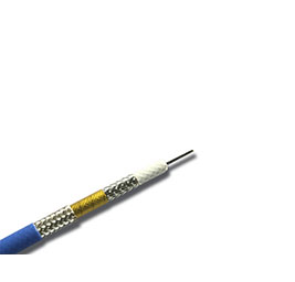
LLF series cables provide a wide range of applications in the current industry, and have very good mechanical phase, attenuation stability, excellent shielding performance and long service life. It is made of low-density PTFE medium and thre...
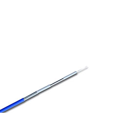
LHF series cables provide low insertion loss within the current industry, and have very good mechanical phase, temperature phase and attenuation stability. Currently, the highest operating frequency of this series is 67GHz. It uses ultra-low...
The LHS superflexible series cables provide the most flexible radio frequency cables at present, and have very good mechanical phase, low attenuation and attenuation stability, and high shielding. And has good processing capacity for power c...
LCF series cables are UHF series economical radio frequency cables, which not only increase the cable attenuation with less floating, but also greatly reduce the cable cost. It is woven with low-density PTFE medium, aluminum foil longitudina...
The AF series cable is a UHF series economical radio frequency cable, which not only increases the cable attenuation with less floating, but also greatly reduces the cable cost. It is woven with low-density PTFE medium, aluminum foil longitu...
The LCS series cable is a UHF series economical radio frequency cable. It increases the cable attenuation in a small float, but greatly reduces the cable cost. It is realized through the cable structure. It uses low-density PTFE medium, alum...
LLS series cables are UHF series economical radio frequency cables, which increase the cable attenuation with less floating, and also greatly reduce the cable cost. It is realized through the cable structure. It uses low-density PTFE medium,...
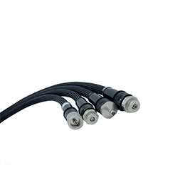
With the continuous improvement and needs of market testing capabilities, Getuo Microwave will develop DC-67GHz high-performance & high-precision test cable assemblies, which are equipped with compression-resistant, torsion-resistant, waterp...
With the continuous improvement and needs of market testing capabilities, Getuo Microwave will develop DC-67GHz high-performance & high-precision test cable assemblies, which are equipped with compression-resistant, torsion-resistant, waterp...
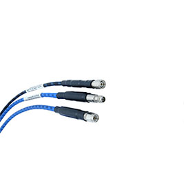
High-strength cable assembly is a flexible cable assembly that can be bent up to 70% and can replace customized semi-steel cables without customizing its own length and bending angle. It is used between communication systems and modules. , I...
UHF series cables provide the lowest insertion loss in the industry, and have very good mechanical phase, temperature phase and attenuation stability. And has good processing capacity for power carrying. This is achieved through the cable st...

News
How to choose a suitable RF cable
1. Visual appearance identification:
1. PVC sheath: the surface can see the regular "unevenness" of the knitting net inside the compression, indicating that the processing technology is good, there will be no relative sliding, and it is a good cable; the appearance is smooth, and no compressed knitting is visible." "Unevenness", pinch the sheath by hand, there is a sense of looseness, which is a poor cable.
2. Check the braiding of the shielding layer: whether the number of braiding is sufficient for braiding the copper wire, check the solderability, scratch the tinned copper wire to see if it is copper wire inside, the hardness of the aluminum-magnesium alloy wire is obviously greater than that of the copper wire; the braided wire is sparse and distributed Uneven, not tightly wrapped with the insulating layer, etc. are bad cables.
3. Check the core wire: diameter-SYV cable is 0.78-0.8mm, SYWV cable is 1.0mm; recently there has been a SYV75-5 cable with a core diameter of 1.0mm. The characteristic impedance of this cable is definitely not 75. Ohm, does not apply to 75 Ohm transmission system.
4. Check the adhesion force between the core wire and the insulating layer: cut the insulating layer diagonally, and pull the core wire in the peeling direction to see if the core wire and the insulating layer are bonded with process materials; a good cable has a larger adhesion force, and a bad one. The cables are not sticking.
5. Longitudinal tensile test: take one meter of cable, strip the core wire, insulation layer, shielding layer, and outer jacket in layers, leaving 10 cm long each. The method is: hold the two adjacent layers of the cable with two hands and pull them in opposite directions; a good cable can’t be pulled with strength, and a bad cable can be pulled out easily without much effort—the elevator cable is very important, many so-called "Elevator cables" all have this problem.
2. Transmission performance test:
The video cable, as the name implies, is a transmission line used to transmit video signals. Since it is used to transmit video signals, at least one must understand the transmission characteristics of the transmission line in the 0-6M frequency band, or in other words, the transmission performance. Here I mainly talk about the "oscilloscope measurement method", for reference, because the oscilloscope is a necessary "weapon" for engineering companies and one of the necessary inspection equipment for qualification review; the following description is based on the already proficient use of the oscilloscope.
1. The color camera video signal can be used as a "standard video signal source": the video output of the camera used in the test project should be 1Vp-p on a 75 ohm load, that is, the bottom end of the line sync head to the highest white level of the video signal "Peak-Peak"; Note that the amplitude of the horizontal sync header is "-0.3V", and the amplitude of the color burst header (4.43M sine wave pulse) is 0.3Vp-p; select the oscilloscope sensitivity and hit the amplitude calibration state. Select a camera with better indicators as the "video source";
2. The test cable should be as long as possible to reduce the measurement error, such as 1000 meters, the cable middle connector must use "F-type connector" and coaxial double pass (cable TV equipment), do not use welding method, because the welding method damages the cable The coaxiality and continuity of characteristic impedance.
3. Measure the DC resistance data of the cable: For example, the SYV75-5 cable is 1000 meters, the DC resistance core wire is 35-40 ohms, and the outer shielding layer resistance is 1000 meters is 24-36 ohms (the number of shielding layers is different, and the resistance is very different) ; SYWV75-5 cable 1000 meters, the DC resistance core wire is 18-22 ohms, the outer shielding layer resistance is 1000 meters is 24-36 ohms; the accumulation of this information is very useful, not only can judge the quality of the cable material, but also used for engineering Check the wiring and pipe quality. For example, when the customer wears the pipe, the line is broken, the resistance value becomes larger, the video signal becomes weak, and the interference that shouldn’t occur is also present. The probability of occurrence of this type of "accident" is very high, but Often overlooked;
4. Measure the high and low frequency attenuation characteristics of the cable: measure the amplitude of the line head and the burst head at the end, and calculate the attenuation with 0.3V as the 0db reference. The line head represents the low frequency attenuation, and the color burst head represents the 4.43M high frequency attenuation. ,——For example: the measured line sync head of 1000 meters is 0.15V, the db number of the attenuation multiple calculated according to 20log is "-6db/1000m", and the measured amplitude of the 4.43M color sync head after 1000 meters attenuation is 30mv, which is 1 /10 times, the attenuation is -20db/1000m; this method can accurately grasp the transmission quality of different cables, and has an intuitive concept of "frequency distortion (high and low frequency attenuation)", you can more accurately measure The difference and performance of SYV and SYWV cables of the same model and structure, compare the differences and performance of products of different manufacturers, and compare the changes of different batches of products from the same manufacturer;
5. The above method can also detect the performance of the video transmission system and equipment: such as the transmission characteristics of each coaxial video cable in the project, the transmission characteristics of the optical transceiver (you can measure good or bad, don’t think it is all ideal), radio frequency transmission, microwave Transmission characteristics, the transmission characteristics of the twisted pair, the distribution characteristics of the video splitter, and the switching characteristics of the matrix host. Pay special attention to when multiple outputs switch the same input signal at the same time. If you find that the more switching channels, the greater the attenuation. It’s wrong, it should remain the same. After the test, you will have a lot of substandard products.
6. Observe the field signal and see if the distortion of the field synchronization position is large (uneven)-it should be very flat;
7. At the same time, you can also use an oscilloscope to observe the low-frequency interference: if the field signal has slow fluctuations, it is 50/100-week interference, there are many "thatch" jumps, most of which are frequency-conversion harmonic interference, disconnect the remote camera, and the cable The inner and outer conductors of the far end are short-circuited, and the interference waveform and intensity can be directly observed with an oscilloscope at the end; this method can also check and test the true performance of the anti-interference equipment.
