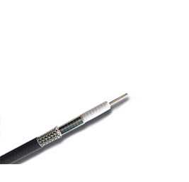
UHF series cable provides the lowest insertion loss in the current industry, and has excellent mechanical phase, temperature phase, and attenuation stability. And has good processing ability for power bearing. This is achieved through a cabl...
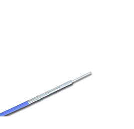
UHS series cable is the super-flexible type of ultra-low loss stable-phase cable. In the market application experience, ultra-low loss stable-phase cable in meeting customer requirements for electrical performance, in actual use, there are s...
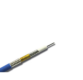
LLF series cables provide a wide range of applications in the current industry, and have very good mechanical phase, attenuation stability, excellent shielding performance and long service life. It is made of low-density PTFE medium and thre...
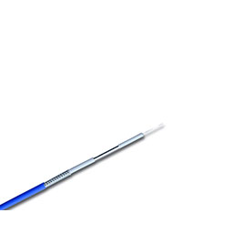
LHF series cables provide low insertion loss within the current industry, and have very good mechanical phase, temperature phase and attenuation stability. Currently, the highest operating frequency of this series is 67GHz. It uses ultra-low...
The LHS superflexible series cables provide the most flexible radio frequency cables at present, and have very good mechanical phase, low attenuation and attenuation stability, and high shielding. And has good processing capacity for power c...
LCF series cables are UHF series economical radio frequency cables, which not only increase the cable attenuation with less floating, but also greatly reduce the cable cost. It is woven with low-density PTFE medium, aluminum foil longitudina...
The AF series cable is a UHF series economical radio frequency cable, which not only increases the cable attenuation with less floating, but also greatly reduces the cable cost. It is woven with low-density PTFE medium, aluminum foil longitu...
The LCS series cable is a UHF series economical radio frequency cable. It increases the cable attenuation in a small float, but greatly reduces the cable cost. It is realized through the cable structure. It uses low-density PTFE medium, alum...
LLS series cables are UHF series economical radio frequency cables, which increase the cable attenuation with less floating, and also greatly reduce the cable cost. It is realized through the cable structure. It uses low-density PTFE medium,...
With the continuous improvement and needs of market testing capabilities, Getuo Microwave will develop DC-67GHz high-performance & high-precision test cable assemblies, which are equipped with compression-resistant, torsion-resistant, waterp...
With the continuous improvement and needs of market testing capabilities, Getuo Microwave will develop DC-67GHz high-performance & high-precision test cable assemblies, which are equipped with compression-resistant, torsion-resistant, waterp...
High-strength cable assembly is a flexible cable assembly that can be bent up to 70% and can replace customized semi-steel cables without customizing its own length and bending angle. It is used between communication systems and modules. , I...
UHF series cables provide the lowest insertion loss in the industry, and have very good mechanical phase, temperature phase and attenuation stability. And has good processing capacity for power carrying. This is achieved through the cable st...

News
About the choice of radio frequency cable
In addition to the frequency range, standing wave ratio, insertion loss and other factors, the correct selection of radio frequency cable components should also consider the mechanical characteristics, use environment and application requirements of the cable. In addition, the cost is also a factor that will never change. Discuss here the various indexes and performance of the radio frequency cable, understanding the performance of the cable is very useful for choosing the best radio frequency cable assembly.
Characteristic impedance
"Characteristic Impedance" is the most commonly mentioned index in RF cables, connectors and RF cable assemblies. Both the maximum power transmission and the minimum signal reflection depend on the characteristic impedance of the cable and the matching of other components in the system. If the impedance is completely matched, the loss of the cable is only the attenuation of the transmission line, and there is no reflection loss. The characteristic impedance (Z0) of the cable is related to the ratio of the size of its inner and outer conductors, and is also related to the dielectric constant of the filling medium. Due to the "skin effect" of RF energy transmission, the important dimensions related to impedance are the outer diameter (d) of the inner conductor of the cable and the inner diameter (D) of the outer conductor:
Z0(Ω) = (138 /√ε) ×(log D/d)
The characteristic impedance of most radio frequency cables used in the communication field is 50Ω; 75Ω cables are used in broadcasting and television.
Standing Wave Ratio (VSWR)/Return Loss
Impedance changes in the cable assembly will cause signal reflections, and this reflection will result in a loss of incident wave energy. The connection between test cable assemblies and the connection between cables/connectors are the main causes of reflection loss. Due to manufacturing reasons, the cable will also produce some VSWR mutations at some specific frequency points.
The magnitude of reflection can be expressed by voltage standing wave ratio (VSWR), which is defined as the ratio of incident and reflected voltage. The smaller the VSWR, the better the consistency of cable production. The equivalent parameter of VSWR is reflection coefficient or return loss.
The VSWR of a typical microwave cable assembly is between 1.1 and 1.5, which is converted into a return loss of 26.4 to 14dB, that is, the transmission efficiency of the incident power is 99.8% to 96%.
The meaning of matching efficiency is that if the input power is 100W, when the VSWR is 1.33, the output power is 98W, that is, 2W is reflected back.
Attenuation (insertion loss)
The attenuation of a cable means the ability of the cable to effectively transmit radio frequency signals. It is composed of three parts: dielectric loss, conductor (copper) loss and radiation loss. Most of the losses are converted into heat energy. The larger the size of the conductor, the smaller the loss; and the higher the frequency, the greater the dielectric loss. Because the conductor loss has a square root relationship with the increase in frequency, and the dielectric loss has a linear relationship with the increase in frequency, the proportion of the dielectric loss in the total loss is larger. In addition, the increase in temperature will increase the conductor resistance and the power factor of the medium, so it will also lead to an increase in loss. For the test cable assembly, its total insertion loss is the sum of connector loss, cable loss and mismatch loss.
In the use of test cable assemblies, incorrect operation will also produce additional losses. For example, for braided cables, bending will increase its loss. Each cable has a minimum bending radius requirement.
When selecting cable components, you should first determine the acceptable loss value at the highest frequency of the system, and then select the smallest size cable based on this loss value.
Average power capacity
Power capacity refers to the ability of a cable to consume heat generated by resistance and dielectric loss.
In actual use, the effective power of the cable is related to VSWR, temperature and altitude: effective power = average power × standing wave coefficient × temperature coefficient × height coefficient
When selecting cables, the above factors should be considered at the same time.
The radio frequency power is often expressed in dBm, and its advantage is the great convenience it brings to the calculation.
transmission speed
The propagation speed of a cable refers to the ratio of the speed of signal transmission in the cable to the speed of light, and is inversely proportional to the root of the dielectric constant of the medium:
Vp = (1/√ε)×100
It can be seen from the above formula that the smaller the dielectric constant (ε), the closer the propagation speed is to the speed of light, so the insertion loss of low-density cables is lower.
Phase stability during bending
Bending-phase stability is a measure of the phase change of the cable when it is bent. The bending during use will affect the insertion phase. Decreasing the bending radius or increasing the bending angle will increase the phase change. Similarly, an increase in the number of bending will also lead to an increase in the phase change. Increasing the ratio of cable diameter/bending diameter will reduce the phase change. The phase change and frequency are basically linear. The phase stability of the microporous dielectric cable will be significantly better than that of the solid dielectric cable.
When measuring with a vector network analyzer, you can use the RTK161 cable provided by BXT. The phase change of this cable is only 3º (10GHz, bending diameter 50mm); if you need more precise measurement, you can add a sheath, but the cost is higher . In the measurement of general communication frequency band (below 3GHz), the low-cost RG214HF cable can be used, which has better phase stability than the commonly used RG214/U.
Passive intermodulation distortion of the cable
The passive intermodulation distortion of the cable is caused by its internal nonlinear factors. In an ideal linear system, the characteristics of the output signal are exactly the same as the input signal; while in a non-linear system, the output signal has amplitude distortion compared to the input signal.
If two or more signals are input to a nonlinear system at the same time, new frequency components will be generated at its output due to the existence of intermodulation distortion. In modern communication systems, engineers are most concerned about third-order intermodulation products (2f1-f2 or 2f2-f1), because these useless frequency components often fall into the receiving frequency band and cause interference to the receiver.
Coaxial cable assemblies are generally regarded as linear devices. However, pure linear devices do not exist. There are always some non-linear factors between the connector and the cable. These non-linear factors are usually caused by the surface oxide layer or poor contact. The following general principles can minimize passive intermodulation distortion:
• In the equipment, try to use semi-steel cables or semi-flexible cables instead of flexible cables
• Use single-strand inner conductor cable
• Use high-quality joints with a smooth surface
• Use joints with sufficient thickness and uniform coating
• Use the largest possible connector (for example, the intermodulation characteristics of DIN7/16 are better than N, and N is better than SMA)
• Ensure good contact between connectors
• Use non-magnetic material joints (such as steel and nickel)
